![]()
Home
About
Tutorial
Gallery
Download
Purchase
Contact
![]()

General geometry - Vertices - Edges - Faces - Elements - Pivot - Texture mapping
We already know that with the help of the menus on the left panel of the program we can create cubes and a number of other basic shapes. But of course they can not be enough for us, so we will now look at adjusting the basic bodies to more complex and richer shapes.
When any body is created on the left panel, it is always set parametrically to the specified values. This makes it easy and fast to construct interesting shapes but thay are always limited by certain regularity or symmetry. If we want to model more precise details or irregular shapes, we need enough freedom to do so, and it will give us the General geometry. Note: This does not apply to cameras, lights and some selected models of complex geometry that must remain parametric.
General geometry is actually open access to the shape of an already created parametric model. For example, in the 3D models in the left panel, select Panel and press the Create button. In the bottom left of the screen, you see four fields for entering the parameters of the Panel. Set it as follows:
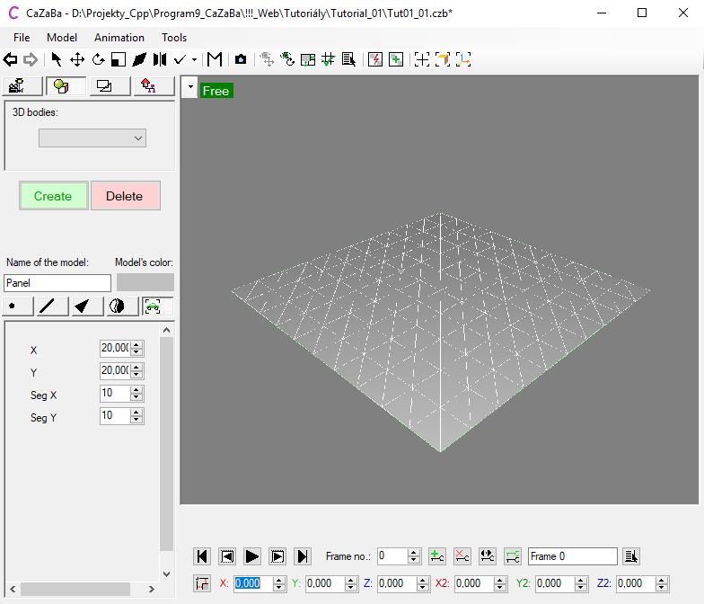
We see that we have constructed square of both wide and long 20 units and divided into 10 segments in both axes. In order to be able to touch the models appearance more gently, we'll convert it to General geometry. The conversion is done for selected models only, while unselected models remain as they were. Please select our model and then choose Model - Convert to general geometry or Ctrl + G. After this operation, we see that the fields for parameter input are gone. Above the space where they were located, there are five buttons, of which it is active the rightmost - Model. After converting to general geometry, we are now allowed by the program to switch to the next four buttons to uncover edit functions for Vertices, Edges, Faces and Elements, which we will now introduce more closely.
Caution: later, general geometry can no longer be converted back to the parametric model even if we modified it in its original form.
To work with the vertices, edges and faces of the model, you need to know better the mouse selection options. To select any model area, just switch to the Edit view and mark the area by dragging left mouse button in the viewport. If you wish to add another region to this selection, hold Ctrl and then drag left mouse button over the desired part of the model. And if you want to cancel some part of the model from the selection, hold Ctrl and Alt at the same time, and again drag left mouse button over the area to be deselected. Finally selection inversion is made by shortcut Ctrl + X and select all by shortcut Ctrl + A.
Make sure you still have a selected panel model - a light green frame is drawn around it and the edges of the model are colored white. If it is not selected, select it by left-clicking the model or by selecting it from the model list ![]() . Now, switch to the Vertices tab at the bottom part of the left panel. The model will be rendered with a number of blue dots that highlight the model's vertices. Try dragging the mouse to select a range of vertices. The blue color means unselected vertices, the red color is the opposite for the vertices selected. You can now turn on the Translation transform on the toolbar and move the selected vertices a bit further. For example along the Z axis.
. Now, switch to the Vertices tab at the bottom part of the left panel. The model will be rendered with a number of blue dots that highlight the model's vertices. Try dragging the mouse to select a range of vertices. The blue color means unselected vertices, the red color is the opposite for the vertices selected. You can now turn on the Translation transform on the toolbar and move the selected vertices a bit further. For example along the Z axis.

Tip: Note that when you now click anywhere outside the model, it will not be deselected. This is because, when editing the vertices, selection is locked only for a particular modified model, and all mouse selections and mouse drag operations now affect only the individual vertices in the model. Another model can be selected by mouse after switching back to the whole model card - fifth button on the far right. This behavior is the same for edges, faces, and elements.
On the vertices edit tab we will now be interested in the top five buttons whose features are as easy as they are named. The Delete button, of course, allows you to delete the selected vertices from the model and at the same time all edges and faces that are related to them.
The Merge button, on the other hand, merges all the selected vertices into one located directly in the arithmetic mean of the selection. At the same time, the resulting vertex will join all the edges and faces that were connected the original vertices.
The Split button causes the faces to separate from each other at this vertex. Instead of one, there will be as many vertices as the faces belonged to the original vertex.
The Match button, like Merge, places all vertices at the arithmetic mean of the entire selection. However, these vertices do not yet merge, but only unify their normal vector. This is practical when we want to get rid of sharp edges between the vertices of the two faces that point each other somwhere else into the texture.
Tip: When transforming edges and faces, the matched vertices behave as one, although each belongs to another faces. So if we move, for example, a faces whose vertex is matched with others, these vertices will also move.
The Unmatch button separates the matched vertices again. It will restore sharp edges between them and such vertices will behave independently when transforming their faces.
The next three buttons deal with some more sophisticated tasks. To use the Create edge button, you must first select exactly two vertices. After pushing a button, of course, a new edge is produced between them these vertices. It is necessary to select no more than actually two vertices, otherwise the program would not know which pair of vertices we want to link in the selection and which not.
The Create face button works similarly to Create edge, but the result is a new face. For this reason, it is necessary to select exactly three vertices for this operation because the program only works with triangular faces.
The Extrude edge button basically allows you to create a new vertex. Respectively to the already existing selected vertex it will create a new edge ending with a new vertex. This is actually a copy of the original vertex. Thanks to this we can gradually expand the shape of the model.
Tip: Edge extrusion can also be applied to multiple selected vertices simultaneously. Caution however, after pressing the Extrude edge button, it appears that nothing happened because the vertices stayed in the original place. That's just apparent. The vertices will be copied and linked to the original vertices. It is just necessary to not lose their selection and by transformation Translation ![]() pull them to another place.
pull them to another place.
These buttons are followed by four separate sections for advanced vertices processing. The first is used to automatically merge / match the vertices of the model.
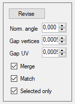
For this operation, under the Revise button, the program chooses vertices from the model according to the following criteria. There will be affected only those vertices whose normal vectors form at most the angle set in the Normals angle field. Together with the distance between the vertices in 3D space up to value in the Gap vertices field and the same in the UV space of the texture with the maximum distance of Gap UV field. If the Merge box is checked, the vertices that meet all of the above conditions are merged into one. If the Match box is checked, all vertices that have not been merged or do not have UV close enough at any of the four levels of UV space are matched. Finally, checking the Selected Only box tells the program that the merge / match should only perform on pre-selected vertices. This allows us to modify only part of the model without interfering with other already finished parts. Conversely, if unchecked, revision is performed for all vertices of the model.
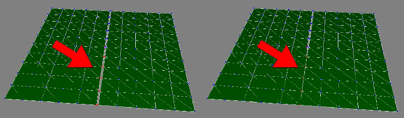
Tip: After pressing the Revise button, only the vertices closest to each other are merged or matched within separate groups. For example, this feature allows you to automatically remove splits between separate faces or sharp edges, etc.
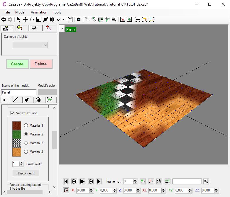
The section below shows a table with four gray frames and radiobuttons "Material #...", which is introduced by the Vertex texturing checkbox. By checking this checkbox, the section opens and allows you to set up up to four different materials on the model. Gray frames are therefore material previews. To work with a particular material, always switch to its respective radiobutton, then the material can be assigned (in the material window) or disconnected (by the Disconnect button). Above all, however, it is also possible with the selected material to "color" the desired area of vertices on the model by simply dragging the left mouse button. Note that when the vertex texturing is turned on, the left mouse button stops selecting vertices, but acts as a paintbrush for painting the particular material. How wide the area on the screen will respond to mouse drags is given by Brush width. To enable again the selection and transformation of the vertices, turn off vertex texturing by unchecking the Vertex texturing checkbox.
This section is also linked to the following section - Vertex texturing export to the file. Here you can export a texture to a file that shows the resulting distribution of the materials we produced in the Vertex texturing section. Depending on the active radiobutton, the appropriate type of texture derived from the associated model materials is exported. The Backg. Color color box is useful when we map the UV coordinates of multiple parts of the model to one texture where remains empty spaces between them. These spaces are filled with this color.
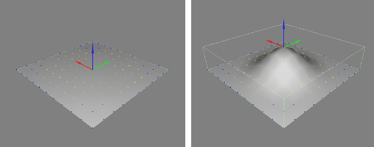
Finally for the last section so far the Extended selection. Like vertex texturing, this is turned on by checking the checkbox that is currently present. However, the left mouse button here does not lose the ability to select and transform the vertices. Instead, an array of a certain width according to Radius appears with the vertices marked yellow to green around the selected (red-marked) vertices. That means gradually lowering weight of the vertices selection out of the selection area. In short the used transformations like Translation, etc. will only have a 100% effect on the red-marked vertices, and with the gradient transition from green to yellow, the transformation effect will decrease. Thanks to that it is possible for example to shape hills from flat plain etc. The weight of the effect on the each vertices is determined by the first half of the curve of the cos(x) function in power of a value in the field Exponent. So the higher the Exponent, the sharper the bulge. For a constant linear climb, enter Exponent = 0.
Edge editing functions are very similar to vertices editing functions. Drag the left mouse button to select the desired edges that will turn red. Unselected edges remain white.
The Delete button again deletes the marked edges and all the adjacent faces at the same time.
The Merge button collapses the vertices of all marked edges to one, and the remaining unmarked edges and faces connects to this vertex.
The Split button separates the faces adjacent to the marked edges. In place of the marked edges a sharp edge is created. However, apart from the Split button on the vertices edit tab, the vertices are not separated individually for each face, but only for each side of marked edges.
The Duplicate button simply duplicates the marked edges and their vertices quickly. If the Preserve faces box is checked, the edges, including the faces that are in between, are copied. Otherwise, only the edges themselves are copied.
Tip: After duplicating, the edges remain in the original location and can visually merge with the original. You need not to lose edges selection and move them further to see that they really copied.
The Extrude faces button will copy the marked edge and insert a pair of new faces between it and the original edge. Because at the moment of the process, the newly created faces have a zero width, the program is unable to tell whether to orient them face up or down. For this reason, the faces can sometimes be overturned. To learn how to solve this problem, please refer to Faces in this tutorial.
Tip: After pressing the Extrude faces button, the edges remain in place. As with extruding edges from vertices, it is also necessary to not lose edge selection and move them further to see that the faces have actually been created.
The Create face button, as the name suggests, creates a face between two edges. However, it is necessary to select exactly two edges and these must be connected with one common vertex. The program uses only triangular faces, so even with this function the selected edges must define sides of the triangle.
Even the functions on the faces edit tab do not differ much from those mentioned above. The faces selection is the same as we already learned from the edge selection. Drag the left mouse button to mark the required faces that turn red. Unmarked faces retain their appearance. It is possible to select the faces also individually by clicking mouse on them.
The Delete button logically deletes all the marked faces. If the Preserve edges check box is selected, only the faces themselves are removed and the edges defined by them will remain. Otherwise, all the edges between the faces will be deleted.
The Merge button, as well as the merging of edges, will collapse the vertices of the marked faces into one, and the edges and faces bound to the original selection will join this new vertex.
The Flip button turns the marked faces inside out. However doesn't disconnect these faces from the surrounding faces, so the shading reveals the transition of the normal vector to the other side around the selection. This feature is especially suitable for correcting incorrectly oriented faces when extruding faces from edges (see above) and the like.
The Revert button inverts the marked faces inside and separates them from the surrounding faces. This makes the faces both inverted and non-inverted to preserve their proper shading. On the other hand, between the inverted and non-inverted part of the model, a sharp edge results in this operation.
The Duplicate button quickly duplicates the marked faces within the model.
Tip: After duplicating, the faces remain in the original location and can visually merge with the original. You need not to lose faces selection and move them further to see that they really copied.
The Extrude polygon button lets you pull out the marked area of the faces outside the surface level. This area is also newly connected around by the faces strip with the original surface. Caution: At the moment of the polygon creation, its lining strip of faces has a zero width. Since the program is unable to determine the correct orientation of the faces, the faces on one side of the polygon will be oriented above the surface, but on the other side under the surface. You must then repair it with Flip or Revert.
Editing elements is very related with editing faces. The only difference is that when selecting it not selects the individual faces but always the entire separate area of faces. It means individual parts that are not linked to other parts of the model. For example sharp-edged cube walls, etc. However, work with the functions on this tab can be combined with the functions on the faces edit tab.
There are only two buttons here. The Detach model button disconnects the marked part of the faces into a new standalone model in the scene.
The Attach model... button will connect the current any external model in the scene from the list that appears when the button is pressed. Attached model takes the material settings from the current model. Caution: Attach can not be made with Cameras, Lights, and some models from Complex geometry.
You have surely noticed that on the first three tabs - Vertices, Edges, Faces - there is one more section of functions called Pivot. Pivot is a point to which the transformations applies. When working with the program, we determine three types of the pivot. The global pivot is the pivot of the whole model and is only relevant for transformations of the model as a whole - it is position coordinates when transforming translation etc. Second one is Own pivot, which is the arithmetic mean position of all the currently selected parts of the model when editing general geometry. You surely noticed that when selecting vertices, edges or faces the transform cursor kept still in the middle of the selection - was in the own pivot. Finally third, the Synthetic pivot is a stand-alone point whose position can be set any time at will when we don't need do transformations by the Own pivot.
When adjusting the vertices, edges, and faces you can always use the radiobuttons Use own and Use synthetic to switch between both pivot types as desired. When editing the vertices, the Synthetic pivot is visible as a distinct purple vertex, which can not be selected. When editing edges and faces, the synthetic pivot is still present but it is not visible. To swiftly place the Synthetic pivot on the Own pivot position simply press the Synthetic = Own button. For example, you can set the position of the synthetic pivot according to the selection of vertices, which you can use to transform selected faces and the like. However, if you want to have the absolute control over the synthetic pivot and set its position manually, go to the vertices edit tab and select Edit synthetic radiobutton. At that point, its coordinates enter as well as the coordinates of the ordinary vertex in the X Y and Z fields at the bottom of the screen or drag the mouse at the cursor. There is still a necessary to have at least one vertex selected in the model, otherwise the pivot will not respond. Note: As long as you won't switch back on the Use own or Use synthetic radiobutton, the program will still expect to enter coordinate for the synthetic pivot and not for the model vertices.
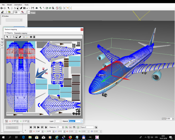
Working with general geometry is not limited only to modeling in 3D space. The vertices of each model have UV coordinates that show their position in the texture. To open the texture mapping window, choose Model - Texture Mapping... or key shortcut Ctrl + Shift + M. Whether the model was or was not a general geometry before, running texture mapping will automatically convert the model to it. A window with two tabs is displayed. At the beginning, the UV Mapping tab is always active, displaying the texture vertex layout. Here, vertices can be edited almost identically as when working in viewports of the main program window.
The second tab Parametric mapping offers additional options for vertex organization in texture, not only parametrically. The first section offers planar, cylindrical or spherical model mapping. You can use the Scale and Offset to specify a particular area in the texture to be mapped. The scale determines the size of the area, and the offset determines the location of the area in the texture. The three fields Alpha, Beta, and Gamma determine the rotation of one of the three projections (planar/cylindrical/spherical) around the space axis. Alpha = Pitch, Beta = Yaw and Gamma = Roll. Mapping will not be done immediately, but only after pressing the Proceed button.
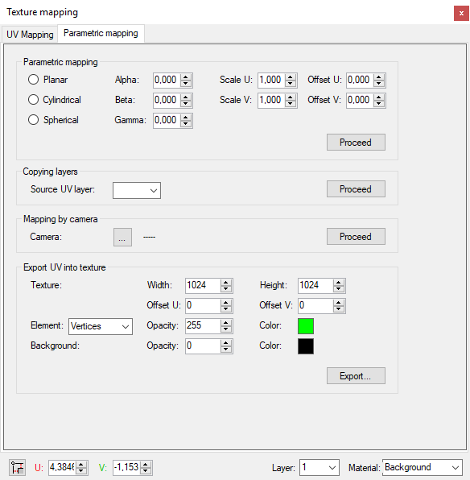
In the next section you can easily copy UV coordinates between the layers of the model materials. At the bottom of the Texture mapping window, select the current layer in the Layer box. Then, in the Copying layers section, set the source UV Layer field to the layer number from where you want to copy the UV Layout of the vertices, and then apply by the adjacent Proceed button.
Mapping by camera is very similar to Parametric mapping. Instead of the type of the projection you just use the Camera button to show the list. There you'll select the camera by which's view you are mapping your body. Apply with the adjacent Proceed button.
Finally, the Export UV into texture section offers saving the UV layout as an image to the disc by the specified parameters.